5. Derive contour lines
We'll continue with the IDW result and will add contour lines.
An easy and quick way to visualise contour lines is to use the Contours renderer in the Layer Styling panel.
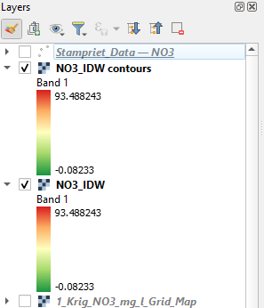
1. Make sure that the NO3_IDW layer is completely visible in the map canvas.
2. Duplicate the layer, rename it to NO3_IDW_contours and drag it above the NO3_IDW layer. Also check the box to make the layer visible.
3. In the Layer Styling panel change the renderer from Singleband pseudocolor to Contours.
4. Change the Contour Interval to 10 m and the Index Contour Interval to 50 m. Change the Contour Symbol to gray.
5. With the Input Downscaling setting you can change the smoothness of the lines. Set it to 9.
The map canvas should now look like this:
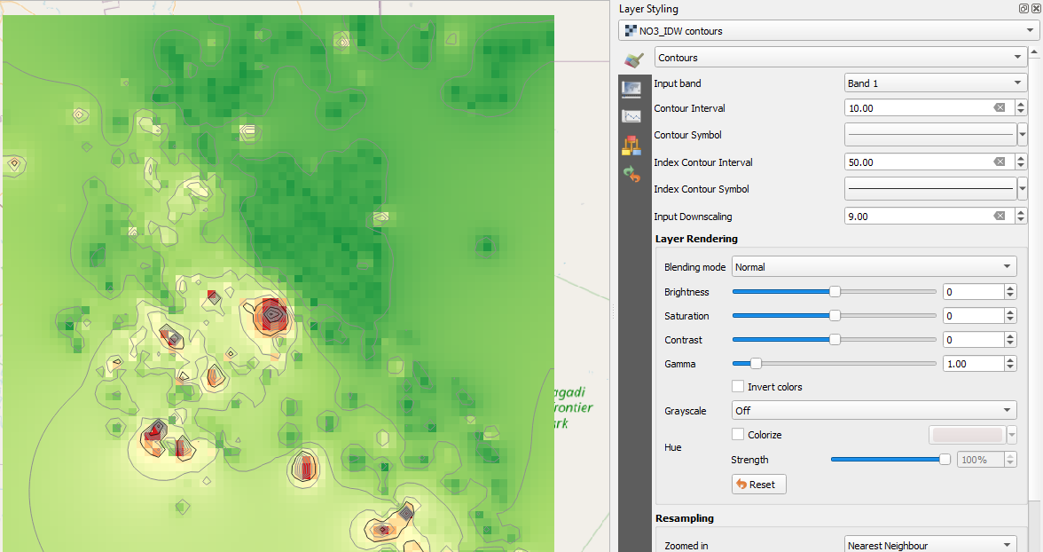
This is nice for visualisation, but not for calculations. Furthermore, we miss the labels with values of the contour lines. So, let's create a layer with contour lines.
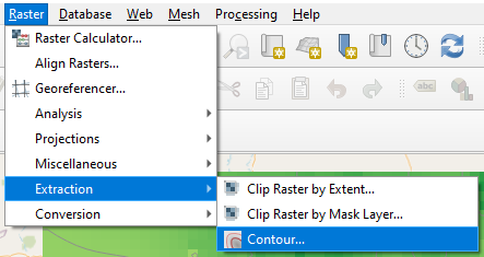
5. Choose from the main menu Raster | Extraction | Contour....
6. Choose the NO3_IDW as Input layer, change the Interval between contour lines to 10 m. Set the Attribute name to Z. Keep the rest as default and save the result as a GeoPackage with the name IDW_contours. Note that you can't save the layer into an existing GeoPackage.
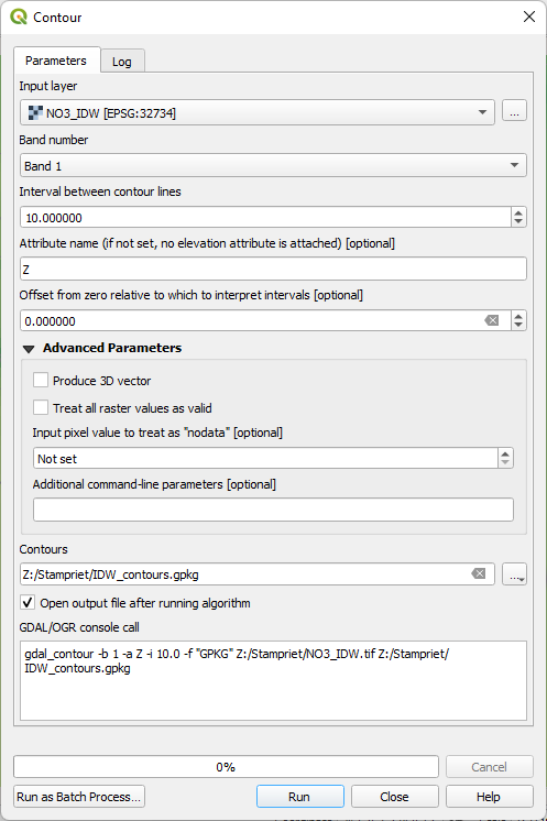
7. Click Run. Click Close after processing.
Let's style the calculated contour lines in the same way as the rendered lines.
Therefore we need to add an attribute for the index lines.
8. Go to the attribute table of the contours layer.
9. Toggle to editing mode and open the Field Calculator.
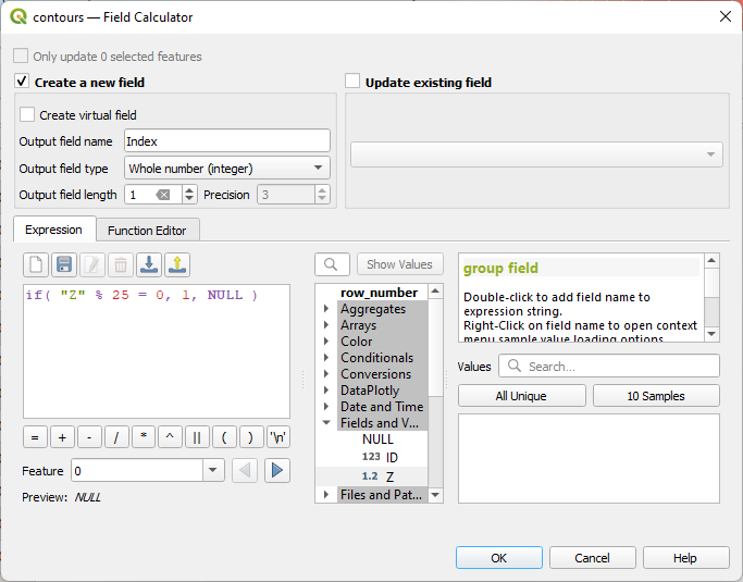
10. Create a new field with the name Index, which has an Output field type of Whole number (Integer) and an Output field length of 1.
11. Create the following expression:
if( "Z" % 50 = 0, 1, NULL )
The expression uses the modulo (%) operator, which returns the remainder of a division. So in this case we divide the value in the Z field by 50. If there's no remainder, we give it value 1, else the Index field gets NULL (which means no data).
12. Click OK and check the result in the attribute table.
13. Toggle off editing mode and close the attribute table.
14. Make sure that the rendered NO3_IDW_contours layer is hidden and go to the Layer Styling panel to style the IDW_contours vector layer.
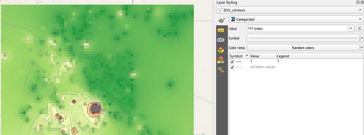
15. Choose the Categorized renderer and select the Index field from the drop down list at Value.
16. Click Classify.
17. Click on the symbol of 1 and make it black. Click on the symbol of all other values and make it gray.
The result now looks like this:
Let's add some labels.
18. In the
Layer Styling panel go to the
Labels 
tab.
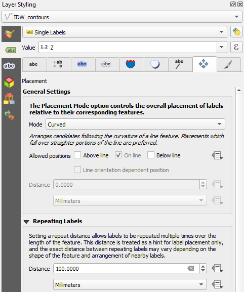
19. Choose Single Labels and Z for the Value field.
20. Go to the Placement

tab. Change the
Mode to
Curved, check the
On line box and uncheck the
Above line box.
21. In the Repeating Labels section, change the Distance to 100 mm. This will allow multiple labels on long lines, making it easier for the reader to find its height.
22. Go to the
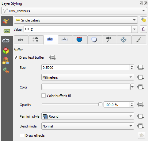
Buffer 
tab. Check the box to
Draw text buffer and set it to 0.5 mm. This makes the labels more readable through the contour lines.
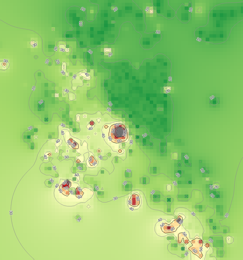
The map should now look like this:
Note that in the Processing Toolbox there are two tools for contours:
The Contour tool is the same as used in this exercise and generates lines. The second tool creates polygons instead of lines.
23. Calculate in the same way contours for the Thiessen and kriging result. Copy the style and label from the IDW contours and compare the results.
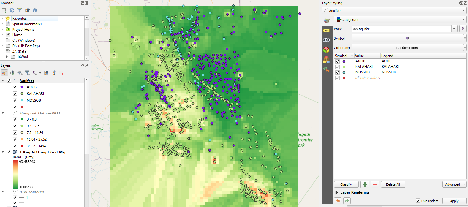
The attribute table of the NO3 point layer also has an attribute aquifer. These are the aquifers of the Stampriet Aquifer System. Maybe the results can be better explained if we look at the different aquifers?
24. Duplicate the NO3 points layer and use the Categorized renderer in the Layer Styling panel to show points from different aquifers in a different colour.
25. Create a nice map with the best result in the Print Layout and explain the result.


 tab.
tab. tab. Change the Mode to Curved, check the On line box and uncheck the Above line box.
 tab. Check the box to Draw text buffer and set it to 0.5 mm. This makes the labels more readable through the contour lines.