Tutorial: Stream and Catchment Delineation
9. Delineate the Catchment
A catchment is an extent or an area of land where surface water from rain, melting snow, or ice converges to a single point at a lower elevation, usually the exit of the basin, where the waters join another water body, such as a river, lake, reservoir, estuary, wetland, sea, or ocean. In order to delineate a catchment we need to have:
- the coordinates of our outlet in the same coordinate system as the map we are using
- the channel network that matches the flow directions as calculated from a hydrologically correct DEM
The outflow point of the Rur catchment is in Roermond, where the Rur enters the Meuse river (Maas in Dutch). The channel network that has been derived in the previous step is in the channels layer. We will however use the channelsstrahler raster layer, because we need to define the outlet exactly on a river pixel.
1. Make sure you have the channels raster layer is on top of the OpenStreetMap layer. You can style the channels layer with a blue ramp, so that the main channel appears in dark blue.
2. Look for the location where the Rur river flows into the Meuse. Note that on the OpenStreetMap the Dutch names are used, because it lies in the Netherlands. Rur is spelled as Roer and Meuse is spelled as Maas.
Note that the delineated channels are not corresponding well with the channels on OpenStreetMap. This can be for the following reasons: (1) Incorrect automatic delineation of streams, which can be caused by errors in the DEM or areas that are too flat, (2) Distortion due to (on-the-fly) reprojection and resampling, and (3) Human influence on the natural course of the channels. The catchment delineation, however, only works when the outlet is defined on a delineated channel, because that corresponds with our flow direction layer. Results can be improved by using different (parameters of) fill sinks algorithms or burning an existing vector layer of the stream network in the DEM.
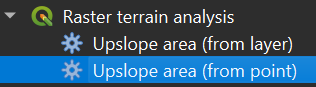
3. In the Processing Toolbox, choose Raster terrain analysis | Upslope area (from point).
4. In the dialog, choose dem_filled as Elevation. Check if the Method is set to Multiple flow direction, because D8 doesn't give good results in this case.
5. At Target point, click  . Now you can click on the outlet location in the map canvas. Choose a pixel on the delineated channel that is close to the real outlet of the Rur in the Meuse (step 2). Make sure you stay upstream of the junction, otherwise you will also delineate a part of the Meuse catchment, which is wrong.
6. Save the result as catchment.tif.
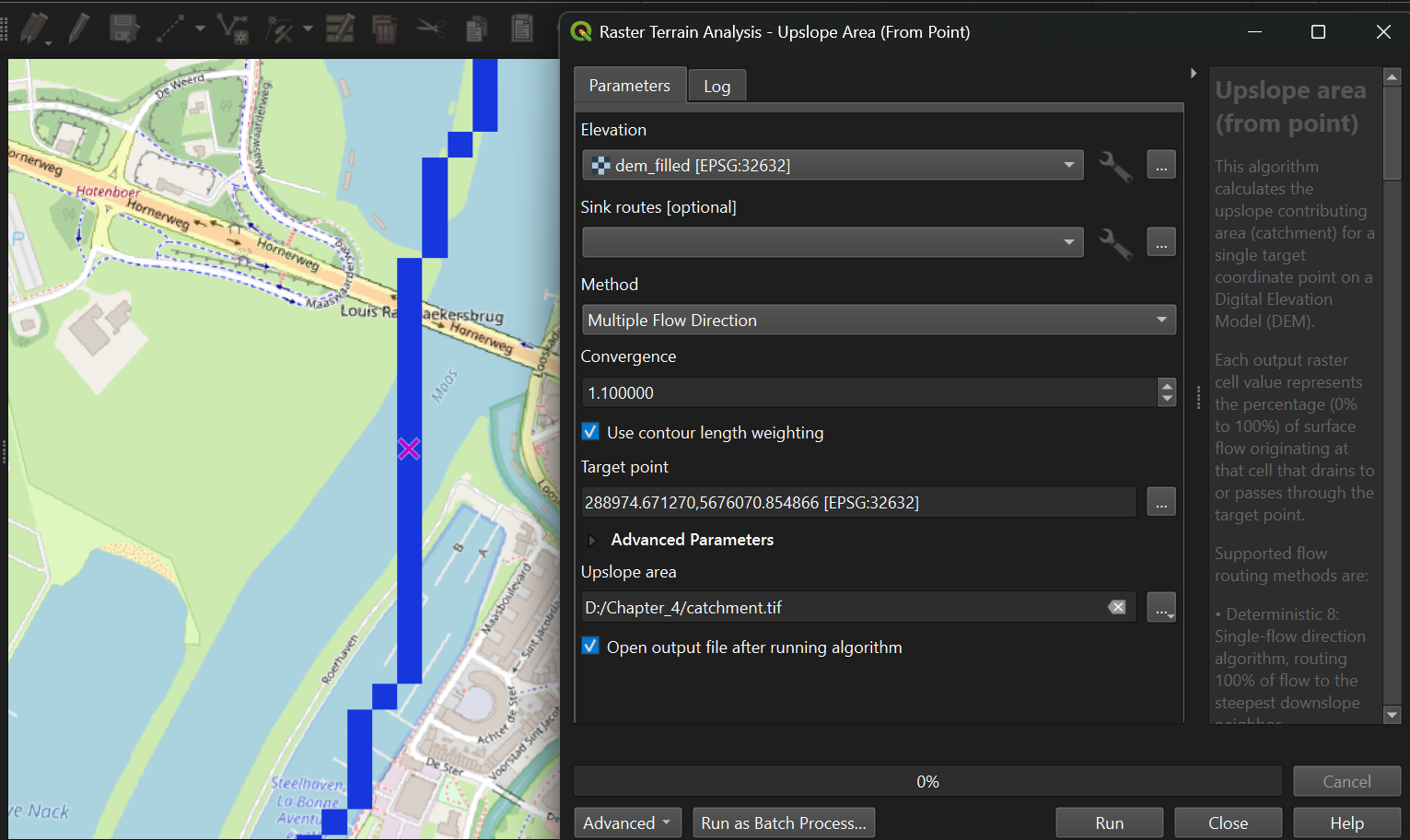
7. Click Run. Click Close after processing.
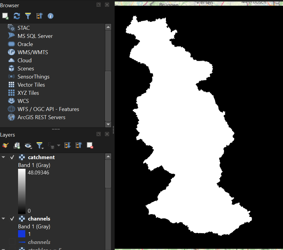
This should be the result.
8. Go to the Raster Calculator and create a Boolean raster with True for cells larger than 0.
In order to overlay the catchment boundary with other data, it is better to convert it from raster to vector (polygon).
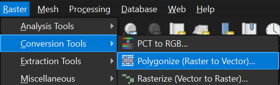
9. To convert the raster layer to vector, go to the main menu and choose Raster | Conversion | Polygonize (Raster to vector).
10. In the dialog choose the Rur_catchment raster as Input layer and save the result as Rur_catchment.gpkg.
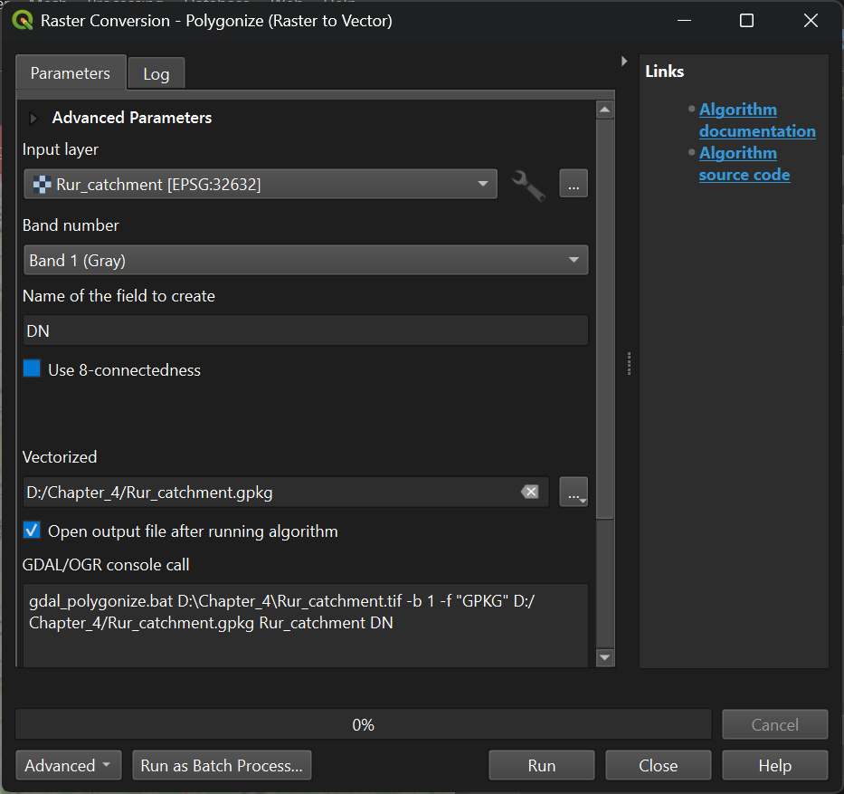
11. Click Run. Click Close after processing.
12. Look at the result. Also check the attribute table (right-click on layer name and choose Open attribute table).
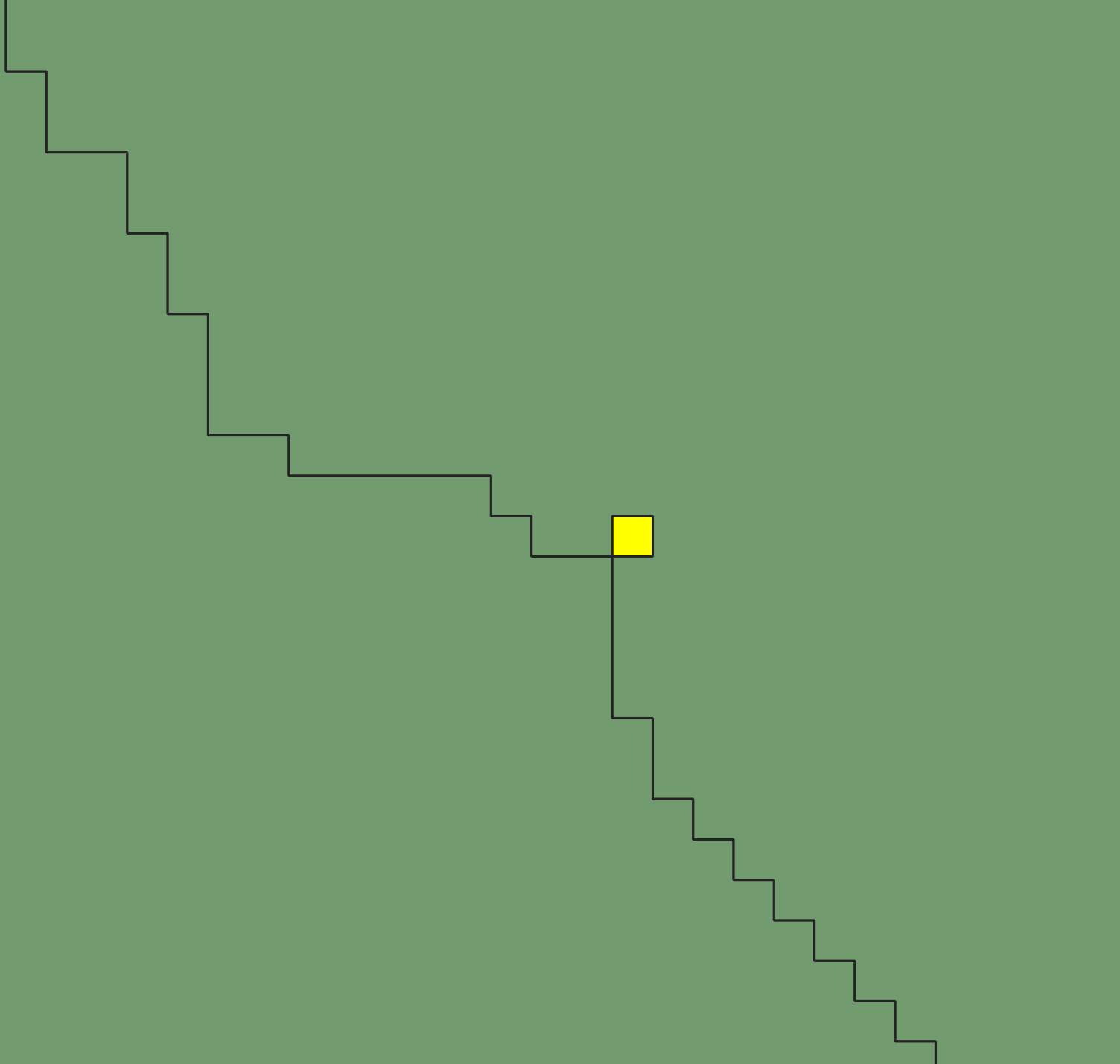
In the catchment calculation, cells belonging to the catchment get a value of 1, while the other cells get a value of 0. During the conversion to polygons, it can happen that geometry errors are introduced. If you find more than one feature with a value of 1 this indicates a geometry error (incorrect topology), because the boundary of the polygon makes a loop (see figure below). This can give errors when we use the polygon for geoprocessing. You can fix those errors with the fix geometry tool in the Processing Toolbox.
Of course we are only interested in the catchment area, so we have to remove the outside polygon.
13. Close the attribute table.
14. In the toolbar, click the Select feature by Area or Single Click tool .
15. Click on the catchment polygon, so it becomes yellow.
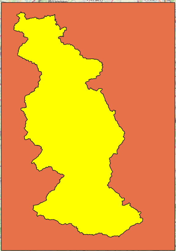
We want to keep this polygon, but remove the other ones.
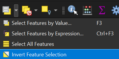
10. In the toolbar. click the Invert Feature Selection tool .
Now the other polygons are yellow:
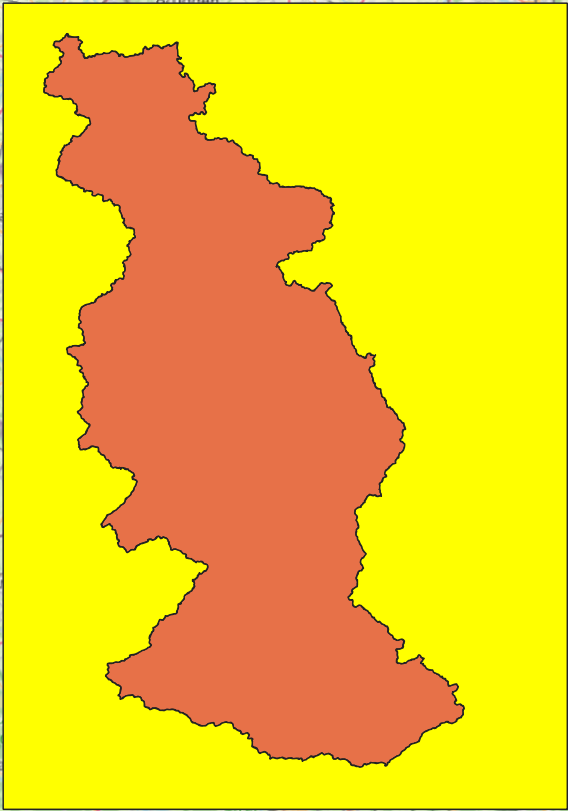
11. Click  to toggle to editing mode.
12. Click  to delete the selected polygons.
13. Confirm that you want to delete the features.
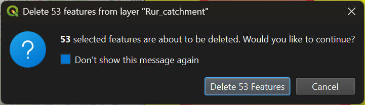
14. Toggle off editing by clicking again, and save the changes.
15. Now remove all unnecessary layers from the layers list so that we have only channels, Rur_catchment, dem_subset, hillshade and OpenStreetMap (in that order).