Tutorial: Calculate Drainage Density
| Site: | OpenCourseWare for GIS |
| Course: | Hydrological Analysis in QGIS |
| Book: | Tutorial: Calculate Drainage Density |
| Printed by: | Guest user |
| Date: | Sunday, 26 July 2026, 10:12 PM |
1. Introduction
Understanding drainage density is fundamental in hydrology. Drainage density, defined as the total length of streams per unit area, provides insight into the efficiency of water movement within a catchment. High drainage density suggests steep terrain, impermeable surfaces, or high precipitation rates, leading to quicker runoff. In contrast, low drainage density is associated with flatter landscapes and permeable soils, resulting in slower drainage.
In this tutorial, we will use QGIS to calculate drainage density for a catchment area. We’ll explore two approaches: a straightforward calculation using polygon and line geometries in the Field Calculator, and a spatially distributed method using the Line Density tool. By the end of this tutorial, you’ll be equipped to derive drainage density maps that are invaluable for hydrological studies, land-use planning, and environmental management.
2. Calculate catchment area
The first step is to calculate the catchment area. We'll use the data provided with this tutorial.
1.Open QGIS Desktop.
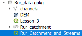
2. In the Browser panel, navigate to the GeoPackage provided with this tutorial: Rur_data.gpkg
3. Expand the GeoPackage and double click on the project Rur_Catchment_and_Streams to open it.
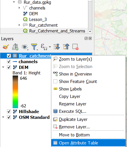
4. In the Layers panel, right click on the Rur_catchment polygon layer and choose Open Attribute Table from the context menu.
5. Click  top open the Field Calculator.
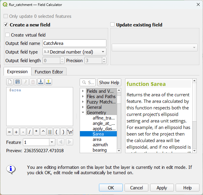
6. In the type CatchArea for the Output field name, choose Decimal number (real) for the Output field type and in the middle panel with functions, expand Geometry and double click on $area to add it to the expression.
7. Click OK to apply and close the dialog.
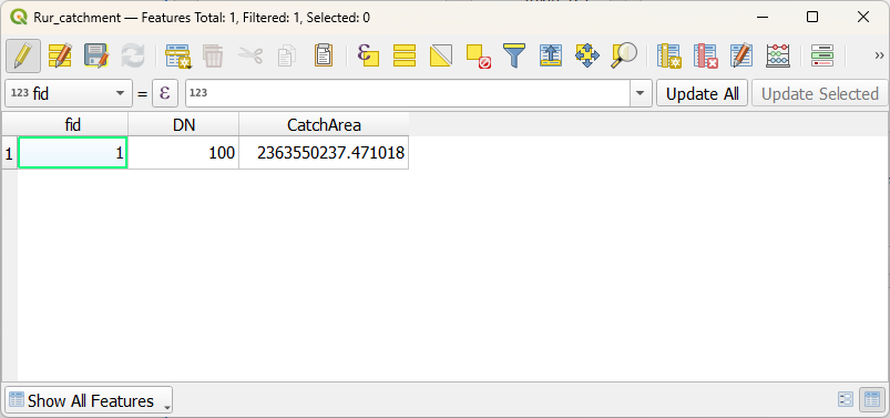
8. Check the result.
The CatchArea field has the surface area of the catchment in map units, i.e. meters.
9. Click  to save the edits and toggle off editing mode.
10. Close the attribute table.
In the next chapter, we'll calculate the total length of the stream network.
3. Calculate total length of stream network
The next step is to calculate the total length of the stream network.
Now the tributaries are in different features with their own length. To calculate the total length, we need to dissolve the segments of the stream network into one feature.
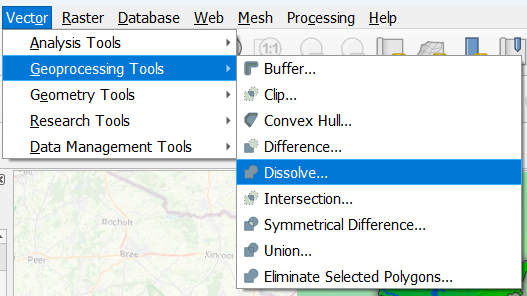
1.From the main menu, choose Vector | Geoprocessing Tools | Dissolve....
2. As Input layer choose channels. Don't choose a specific Dissolve field, so all features will be dissolved into one new feature. Optionally, you can save the result to the GeoPackage.
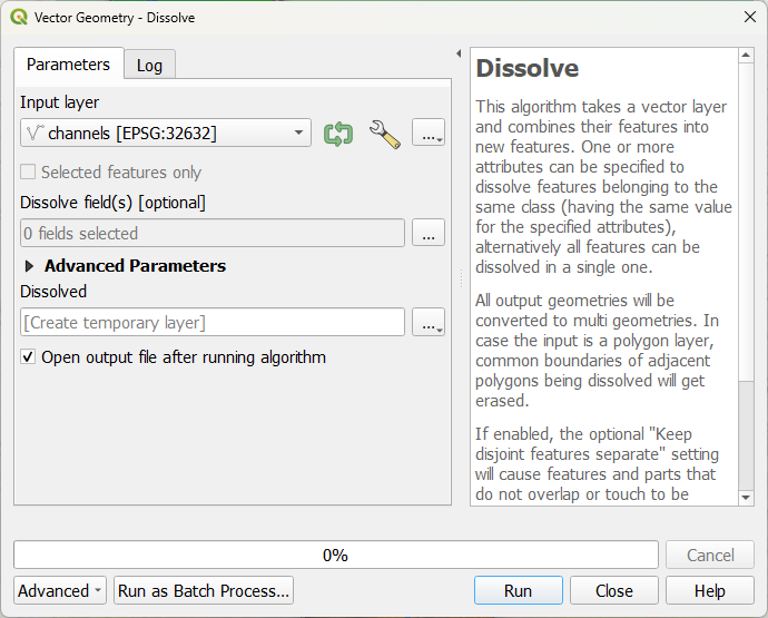
3. Click Run and click Close after processing.
4. Open the attribute table of the dissolved layer.
Now you see that the stream network became one feature. The length field, however, has an incorrect value, because it's not the total length of the new feature, but the length of one of the dissolved segments. Let's calculate the total length of the stream network.
5. Click  to go to the Field Calculator.
6. For Output field name type StreamLength, choose Decimal Number (real) for Output field type and add the $length function to the expression.
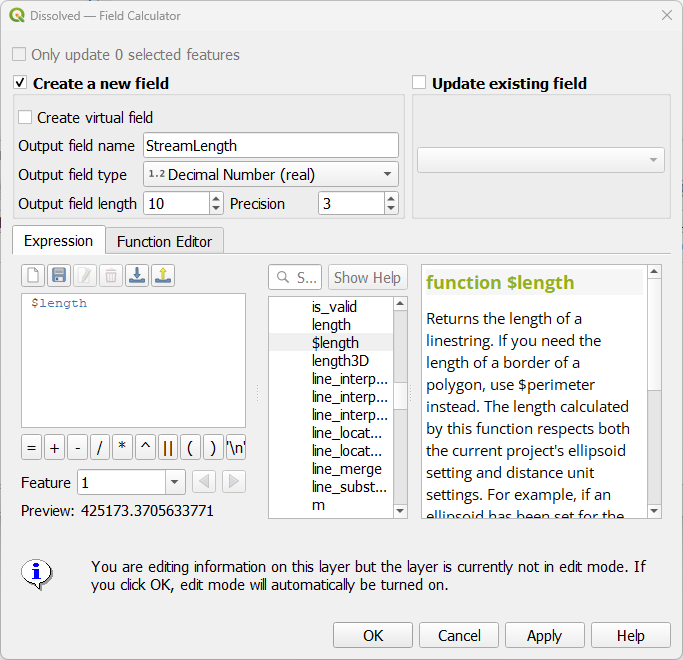
7. Click OK to apply the expression and close the dialog.
8. Click  to save the result and toggle off editing mode.
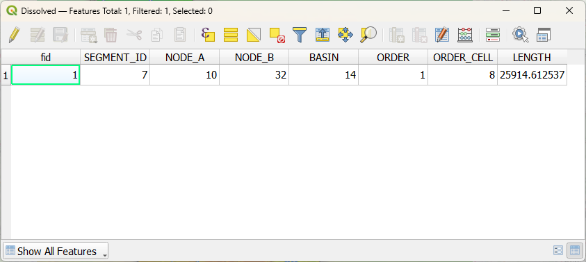
Now the attribute table looks like this:
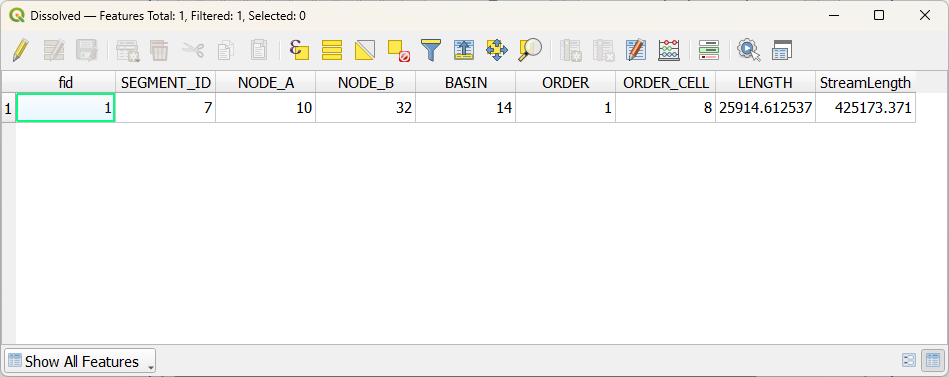
The StreamLength field gives the total length of the stream network in map units, i.e. meters.
In the next chapter, we'll calculate the drainage density.
4. Calculate non-spatial drainage density
Drainage density is defined as the total length of streams per unit area. We have calculated the catchment area, which is the CatchArea field in the Rur_catchment polygon layer. We have also calculated the total length of the stream network, which is the StreamLength field in the Dissolved layer. To perform the calculation, we need to have both values in the Rur_catchment polygon layer. We can do this with a spatial join.
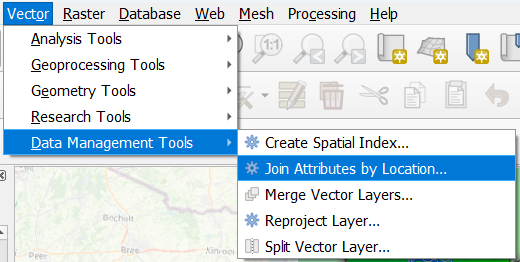
1.In the main menu go to Vector | Data Management Tools | Join Attributes by Location....
2. Make sure that you choose Rur_catchment as the layer to Join features in By comparing to Dissolved. Choose StreamLength as the field to add. Keep the rest as default.
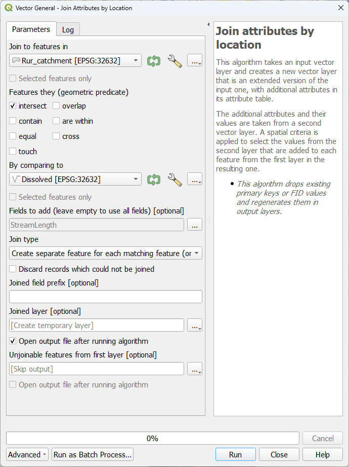
4. Click Run and click Close after processing.
5. Open the attribute table of the Joined layer and check the result.
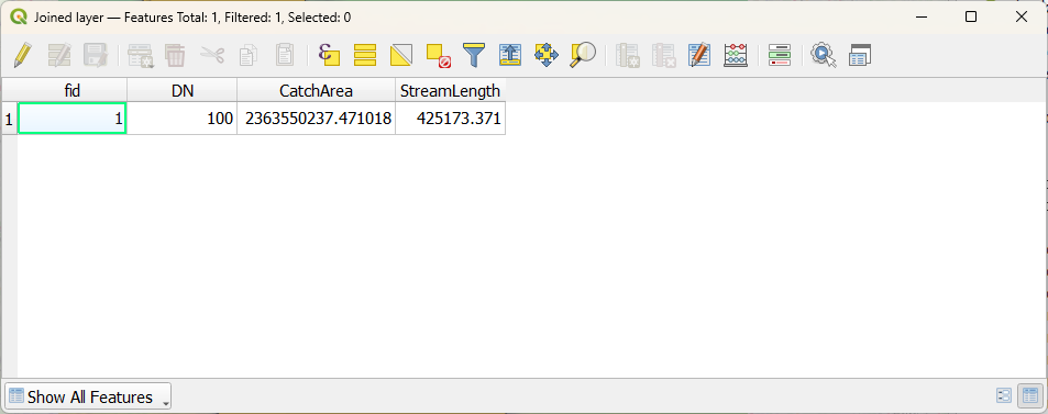
Now we can easily calculate the drainage density with the Field Calculator.
6. In the attribute table, click  to open the Field Calculator.
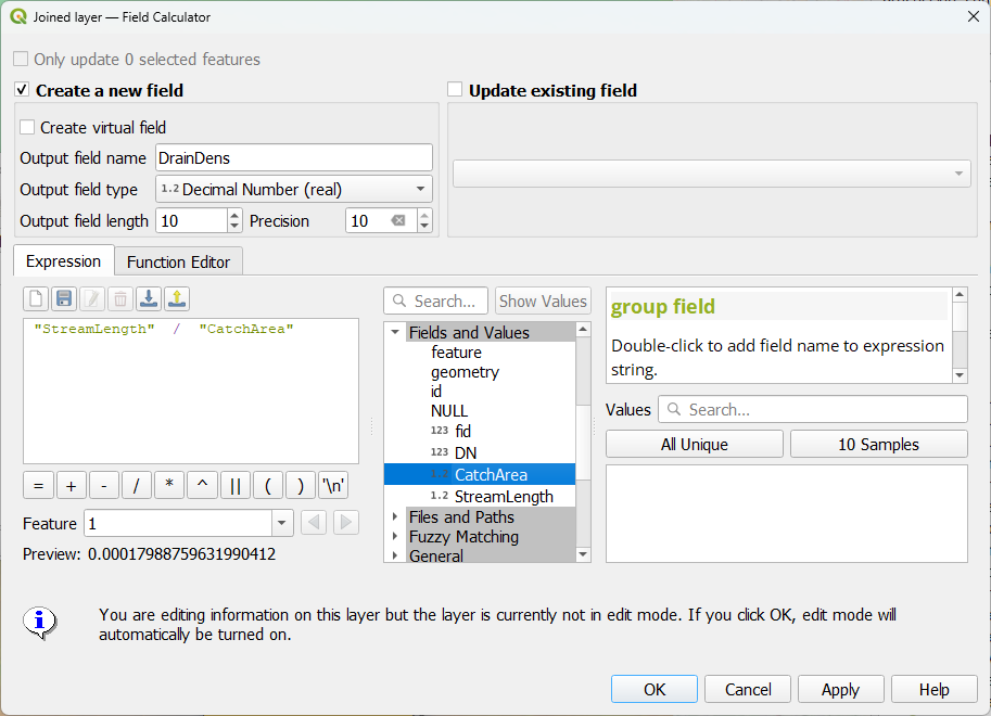
7. Type for Output field name DrainDens. Choose Decimal Number (real) as Output field type and change Precision to 10, because we will have a small number with many decimals.
8. Create the expression
"StreamLength" / "CatchArea"
by clicking the field names under Fields and values in the middle panel.
9. Click OK to apply the expression and close the dialog.
10. Click  to save the result and toggle off editing mode.
Now we can see the result.
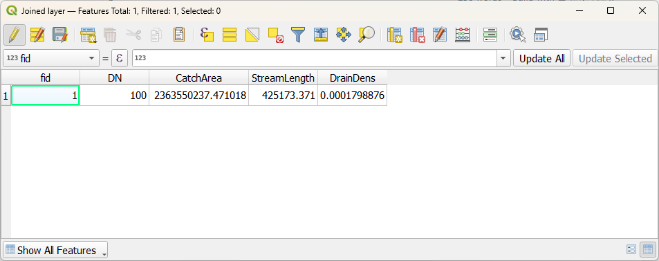
This is one value for a catchment. In the next chapter, you'll learn how to calculate a spatial drainage density.
5. Calculate spatial drainage density
In the previous chapter, you've calculated a non-spatial result for the drainage density of a catchment. In this chapter we'll use the Line density tool to calculate a more spatially explicit result.
1.Click  in the toolbar to open the Processing Toolbox panel.
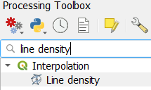
2. In the Processing Toolbox, double click on the Interpolation | Line density tool.
3. In the Line density dialog, choose Dissolved as the Input line layer. Change the Search radius to 10 km and the Pixel size to 1 km. These values depend on the size and properties of your catchment.
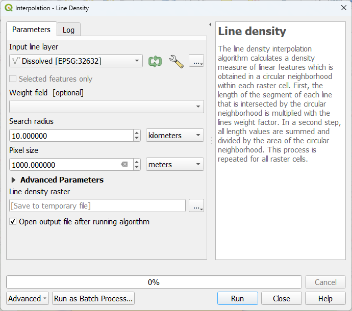
4. Keep the rest as default and click Run. Click Close after processing.
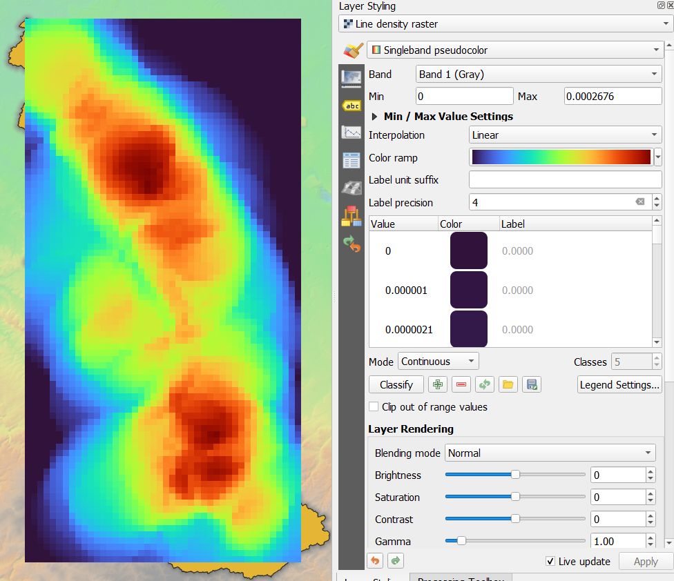
5. Style the result with a ramp.
6. Conclusion
Now you've learned two methods to calculate drainage density.
This video shows the steps: