Tutorial: Editing Point Clouds
| Site: | OpenCourseWare for GIS |
| Course: | Point cloud processing with QGIS and PDAL wrench |
| Book: | Tutorial: Editing Point Clouds |
| Printed by: | Guest user |
| Date: | Wednesday, 29 July 2026, 5:48 AM |
1. Introduction
The most recent functionality introduced is the ability to edit point cloud datasets. The main editing functionality was introduced at QGIS v 3.42 and there will be additional editing features added at QGIS 3.44. Editing takes place in the 3D View.
Note: editing is not available for Virtual Point Cloud layers. This feature is only available for Cloud Optimized Point Clouds (COPC). Additionally, it is only possible to edit the attributes, not location of points.
In the next section, we'll first setup the 3D view. You can use the results from the previous tutorials. The example in the tutorial is Kings Garden (Denmark) used in the original workshop by Kurt Menke and Saber Razmjooei. You can download that dataset from Dataforsyningen from this Google Drive link.
2. Setup the 3D view for editing
1. Open your Kings garden QGIS project.
2. Make sure you have the copc.laz file as the only visible layer.
3. Open your 3D view.
TIP: You can go to View | 3D Map Views and choose the view you’d like to open.
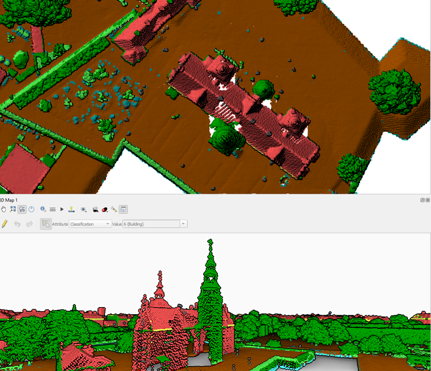
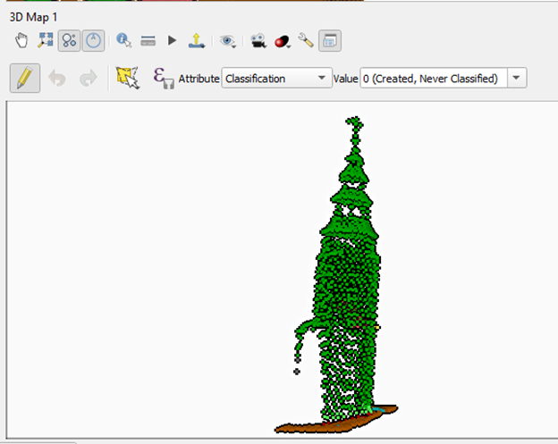
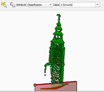
4. Notice that the castle in the center of the moat (Rosenborg Castle) has the main tower classified as High Vegetation. This is incorrect, so you’ll fix it.
Editing Tips
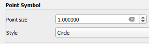
- Use a Point Symbol Style of Circle instead of Square. It can make it easier to see the points.
- Under Layer Rendering set the Draw Order to Bottom to Top so the points are organized by their Z values.
Note: If you have a large point cloud dataset, this setting can increase rendering time.
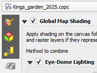
- Enable Eye Dome Lighting in your 3D view. This makes it easier to distinguish features. You can also enable Eye Dome Lighting in your 2D View. To do this, open your Layer Styling panel and select the Shading Renderer tab
 . Here you can enable Global Map Shading and Eye-Dome Lighting.
- It is very useful to have both your 2D and 3D view docked so you can work with both while editing.
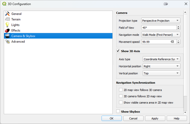
- It is best to use a Projection type of Perspective Projection in your 3D view. This is the default, but you can check your settings by clicking on the Settings button
 in your 3D view. In the 3D Configuration dialog, choose the Camera & Skybox tab. You’ll find the Projection setting under Camera.
 - It may also help to choose a Navigation mode of Walk Mode.
Now we're ready to edit.
3. Change the classification of points
Let's start editing.
1. Navigate so that you get an oblique view of the misclassified tower.
2. Click the Show Editing Toolbar button ![]() .
.
3. Click the Toggle Editing button ![]() to enable editing.
to enable editing.
4. The workflow choosing the Attribute you will be editing and then select the Value you will be assigning to selected points. After setting the Attribute and Value, use the select tool(s) to assign the new values to specific points.
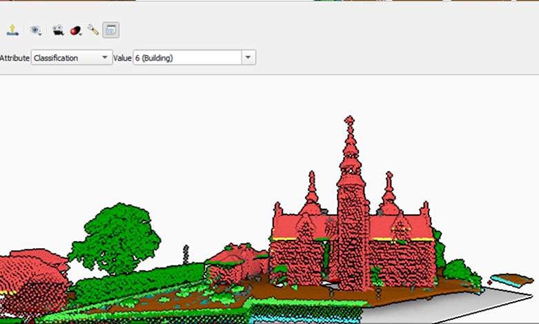
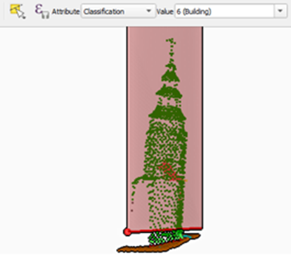
5. Here you will set the Classification value to Building.
![]()
Notice that you can select any attribute. Here we are working with the Classification attribute, but all the point cloud attributes are available to you.
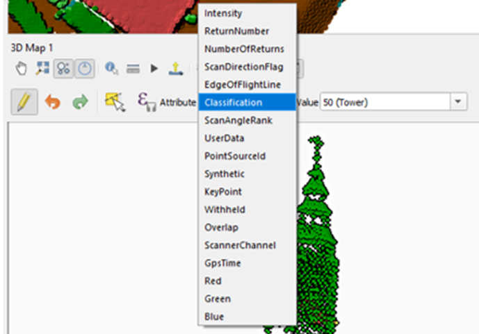
You can also create a new classification attribute value. For example, you can type in the Value box a new Classification value. If you wanted to create a new classification for towers with a value of 50 you would type 50() into the value box.
![]()
At that point you will then need to add that class to your 2D rendering by clicking the Add button ![]() . You will find this below the classification in the Layer Styling panel. After adding the new class, assign a color and a Legend value. In this example, any points you assign as Tower will be shown in hot pink.
. You will find this below the classification in the Layer Styling panel. After adding the new class, assign a color and a Legend value. In this example, any points you assign as Tower will be shown in hot pink.
![]()
6. Using the Change Point Cloud Attribute button ![]() . select the tower points. Use the same steps you use to digitize: left-click to add vertices and right-click to finish.
. select the tower points. Use the same steps you use to digitize: left-click to add vertices and right-click to finish.
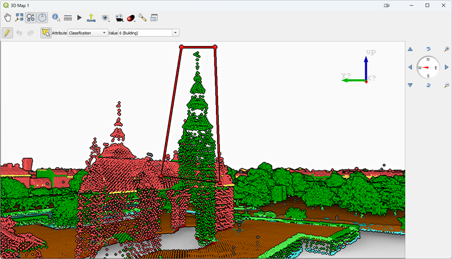
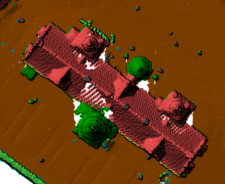
7. After you finish the points will be reclassified to Building.
8. If you aren’t satisfied with the selection of points you have changed you can click the Undo button ![]() or Ctrl-Z.
or Ctrl-Z.
In the next section, you'll learn how to constrain the selection of points.
4. Constraining the Selection of Points
An important note is that when selecting points as shown above, all the points behind the tower will also be reclassified. So you often need to constrain the selection in some way. In this example, you only want to select tower points. One way to do this is to constrain the 3D view extent.
1. To do this open the Settings of your 3D view by clicking on the Settings button ![]() .
.
- Switch to the General tab where you can set the extent of the 3D view.
- In your 2D map canvas, zoom into the building.
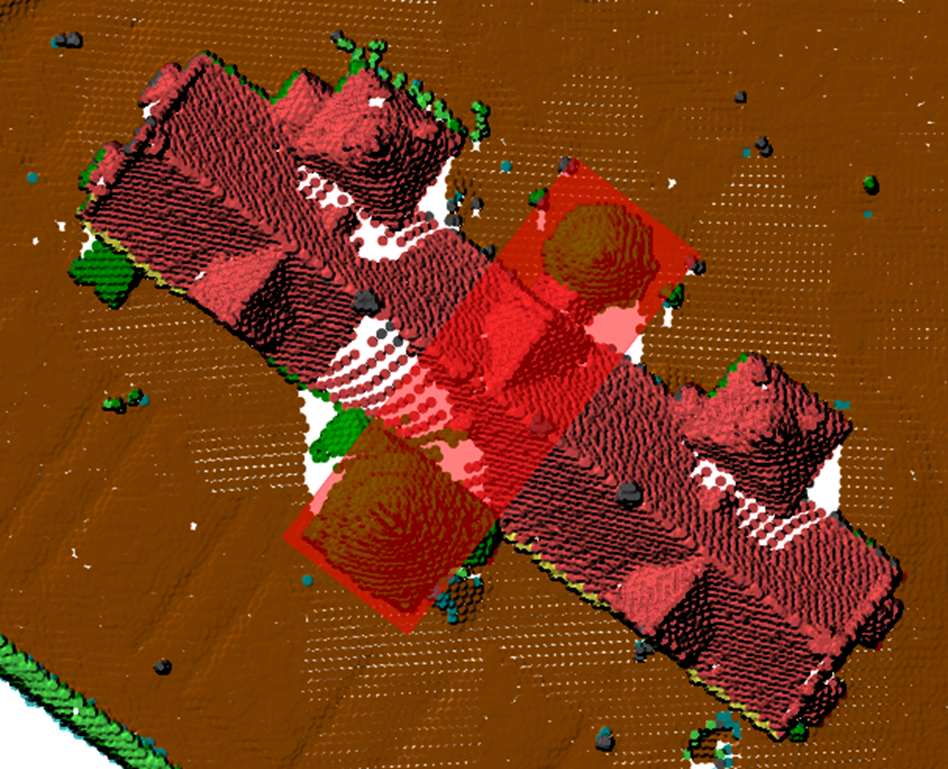
- Click the option in 3D View Settings to Draw on Canvas, and trace a box around the misclassifed tower.
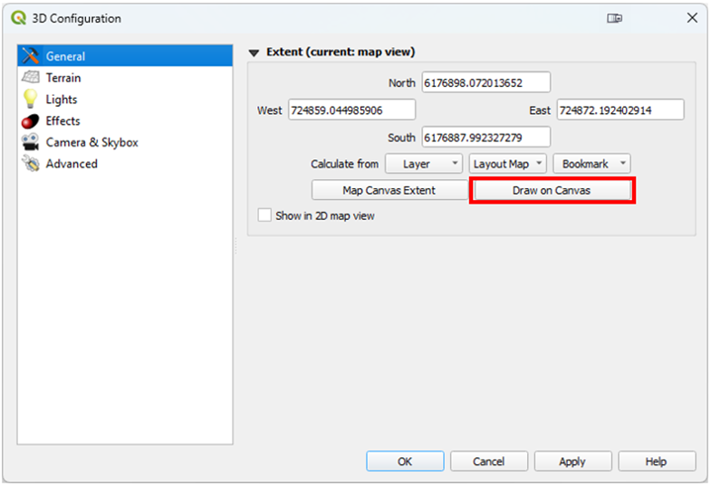
- Your 3D View will now be constrained to that area making it easier to select just the tower points.
2. The goal is to successfully reclassify the tower points to building. When you are finished editing, Toggle out of editing mode and Save your edits.
Some of this is difficult without the full selection of tools coming in QGIS v 3.44 or later. These tools are described in the next section.
5. Editing Tools
QGIS v 3.44 Solothurn comes with a larger set of point cloud editing tools. The next subsections give an overview.
5.1. Selection tools
There are several new selection tool options.
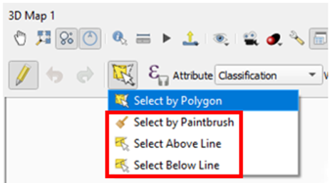
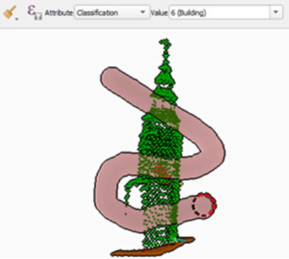
Select by Paintbrush
This option allows you to select points by painting with a paintbrush to select and edit the point values. To adjust the radius of the paintbrush, use the mouse wheel.
Select Above Line
This options allows you to draw a line (defined by 2 points) above which all the points will be edited.
Select Below Line
This options allows you to draw a line (defined by 2 points) below which all the points will be edited.
5.2. Filtering
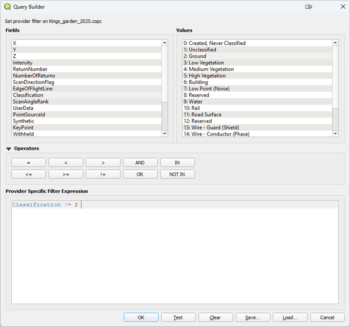
There is also a Filtering ![]() option. This allows you to write an expression which will limit the points you can select. For example, you can choose to select only points which are not Ground:
option. This allows you to write an expression which will limit the points you can select. For example, you can choose to select only points which are not Ground: Classification != 2. When you are finished with the Filter, you must clear the expression to disable it.
5.3. Cross Section Tool
This cross section tool allows you to define a rectangular area to for which you can create a cross section.
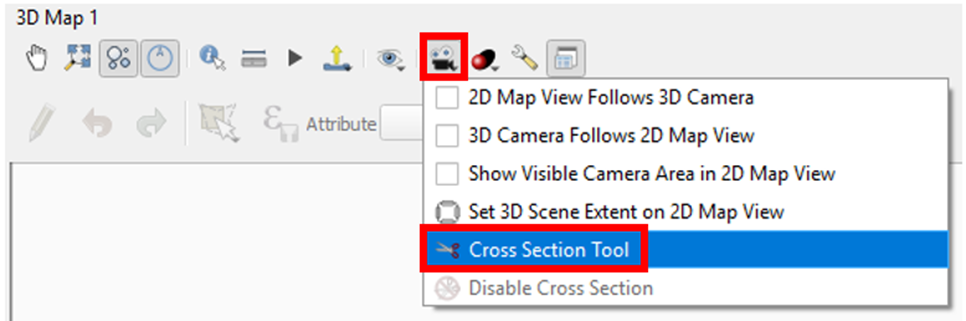
1. To enable the cross section tool find the Camera ![]() button in your 3D View toolbar and choose Cross Section Tool.
button in your 3D View toolbar and choose Cross Section Tool.
2. Then in your 2D View pick two points and the width you want to cross section. QGIS will basically spatially filter the points to exclude everything beyond your defined cross section rectangle.
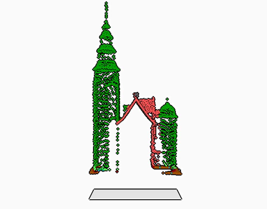
3. The result appears as a cross section in your 3D View.
Note: You can eliminate the gray rectangle below by entering the 3D Settings and on the Terrain tab choosing a Terrain Type of Flat Terrain.
This provides another method of isolating specific points for editing, display or making measurements. This is another good option when the area you are needing to isolate does not fit within a square you can draw on the Map Canvas. It can be especially effect for editing when combined with Filtering.
When combined with constraining the 3D View, these tools allow you to precisely select the points which need to be edited.