Create a Graphical Model for the HAND Algorithm
Completion requirements
4. Add Processing Algorithms to the Graphical Model
Now we can add algorithms for our calculations.
First we need to assign a unique value to each cell of the drainage raster in order to derive the catchments of each cell of the drainage.
1. In the upper left panel of the Model Designer click on the Algorithms tab.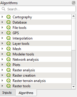
Here you'll recognise most of the tools that are available in the Processing Toolbox. Also the tools from the Processing Provider plugins are included, which means that you can create models which mix algorithms from different processing providers.
2. Use the search box to find the PCRaster uniqueid algorithm.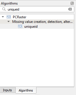
3. Double-click on the uniqueid algorithm.
4. In the uniqueid dialog:
- type at Description: assign unique values to drainage cells.
- change Using model input to Drainage (boolean)
- Keep the Output unique id raster field empty. This field is only used if we want the (intermediate) output to be written to a file and that the user can choose the output file in the dialog. In this case we don't need that.
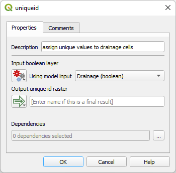
5. Click OK.
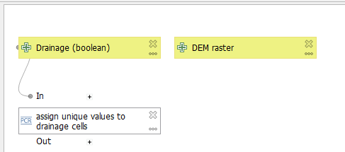
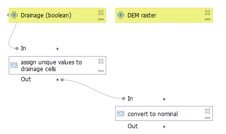
You now see that a white box has been added with the description as a label. You can resize the box as needed or drag it to another position. It will remain connected to the input that was defined in the dialog.
The unique value cells are in the scalar data type. For the catchment delineation of these cells, they need to be converted to the nominal data type.
6. In the Algorithms panel search for the tool to convert the data type.
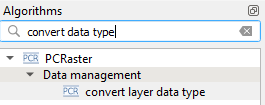
7. Double-click on the convert layer data type algorithm and fill in the dialog:
- Change the Description to Convert to nominal
- Use the drop-down menu under Input raster layer to choose Algorithm Output.
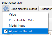
Note that we only have one output, so that's automatically selected. If you have multiple algorithm outputs you can choose it at Using algorithm output. - Change the Output data type to Nominal.
- We're not saving the intermediate result, so we leave the Output raster layer field empty.
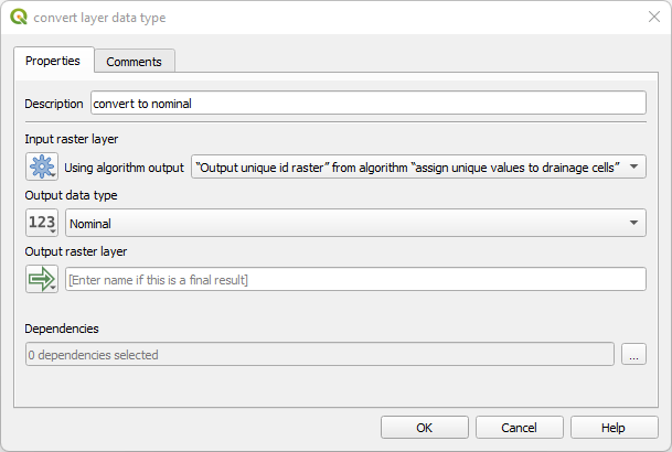
8. Click OK to add the algorithm to the Model Designer.
Now we need to calculate the flow direction raster (LDD) from the DEM. This is a time-consuming step, so instead you could also later add the LDD as an input that was pre-calculated.
9. Search for the lddcreate algorithm in the Algorithms panel.
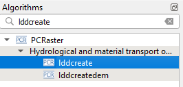
10. Double-click the lddcreate algorithm to fill in its dialog as follows:
- At description type: calculate flow direction
- Keep the rest as default
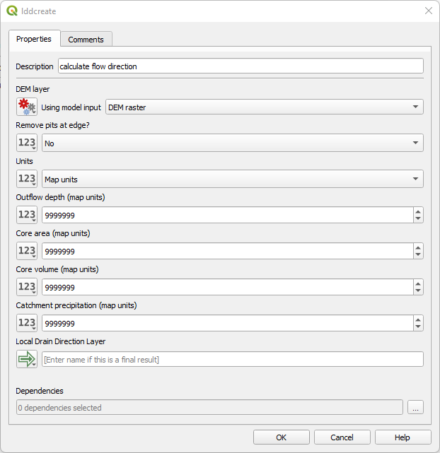
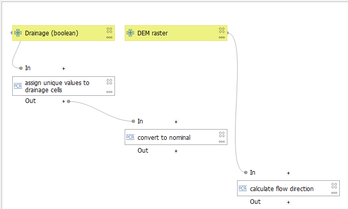
11. Click OK to add the algorithm to the Model Designer.
Now the algorithm is linked to the DEM raster input.
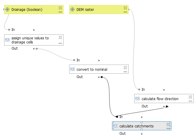
The next step is to calculate all catchments for the nominal cells of the drainage layer. We'll use the subcatchment algorithm, because we don't want overlaps of downstream subcatchments.
12. Add the subcatchment algorithm.
13. In the subcatchment dialog:
- change the LDD layer to the output of calculate flow direction.
- change the Outlet layer to output of convert to nominal.
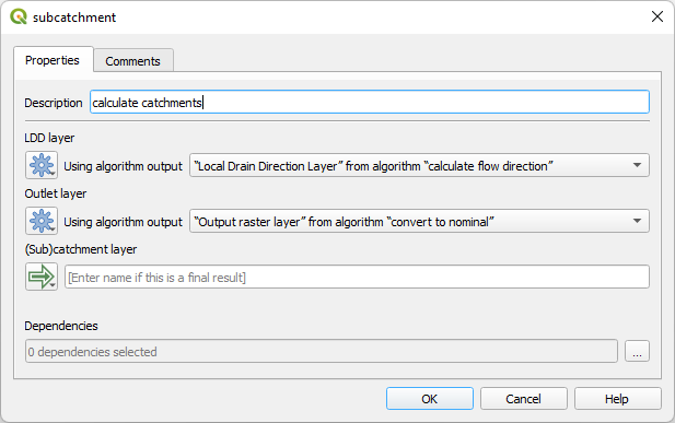
14. Click OK to add the algorithm to the Model Designer.
15. Drag the box to a better position.
Now we need to calculate the minimum elevation for each catchment. For that we'll use the areaminimum algorithm.
16. Add the areaminimum algorithm with the following parameters in the dialog:
- For Description type: calculate lowest elevation per catchment.
- For Class raster layer choose the output of calculate catchments.
- For Input ordinal or scalar raster layer choose the DEM layer.
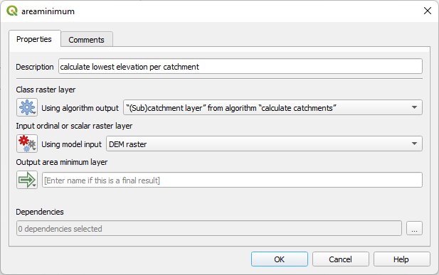
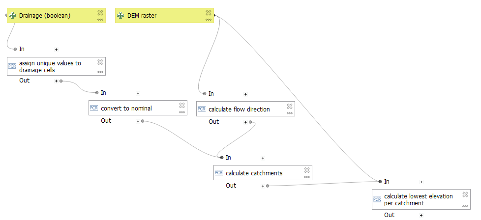
17. Click OK to add the algorithm to the Model Designer. Rearrange the boxes if needed.
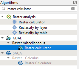
We can now calculate the height above the drainage by subtracting the lowest elevation in a catchment from the elevation of each cell in the catchment. For that we can use the Raster Calculator.
18. In the Algorithms panel search for the GDAL Raster calculator. There are many others, so make sure you pick the correct one, which works best.
19. In the Raster calculator dialog:
- Change the Description to: calculate HAND
- Input layer A should be defined as the DEM with raster band 1 (we only have single-band rasters here).
- Input layer B should be defined as the output of calculate the lowest elevation per catchment with band 1.
- At Calculation in gdalnumeric syntax type:
A-B
Where A and B refer to the layers defined above. - Output raster type should be set to Float32, because it's continuous data
- At Calculated type Output HAND raster, because now we'll write the final result to disk.
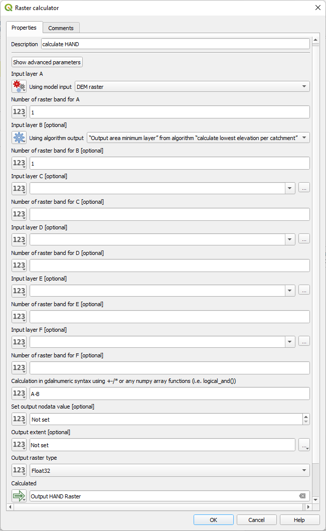
20. Click OK.
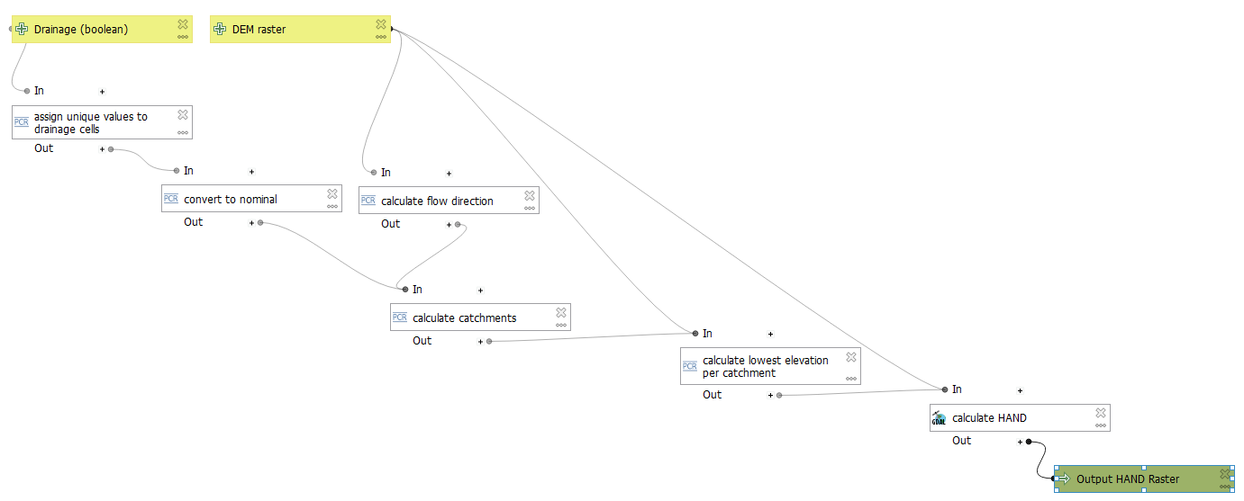
Now our model is ready.
In the next section we'll add a help text for the user.