
Tutorial: Stream and Catchment Delineation
9. Delineate the Catchment
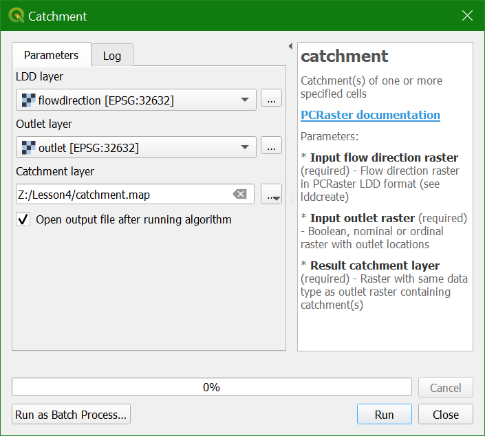
3. Click Run and Close the dialog after processing.
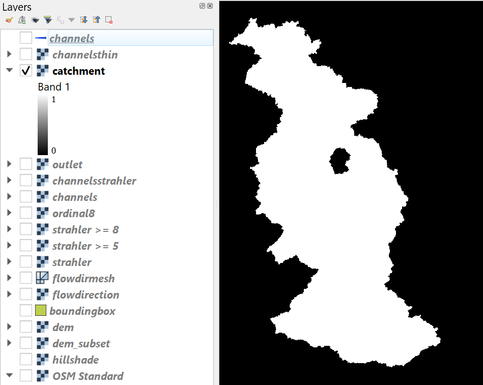
The result should look like the screenshot in the figure below if you zoom to the extent of the layer. The result is a nominal raster with a cell value 1 for the catchment and 0 for outside the catchment. Nominal, because our outlet raster was defined
as nominal data type. If the outlet.txt file had more coordinates of outlets, each catchment would have had cells with the value of the corresponding outlet cell. If you have subcatchments with outlets upstream of a higher order catchment,
you can use the PCRaster subcatchment tool to avoid the overlap.
In order to overlay the catchment
boundary with other data, it is better to convert it from raster to vector (polygon).
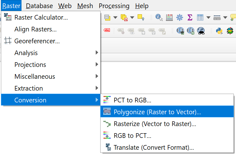
4. To convert the raster layer to vector, go to the main menu and choose Raster | Conversion | Polygonize (Raster to vector).
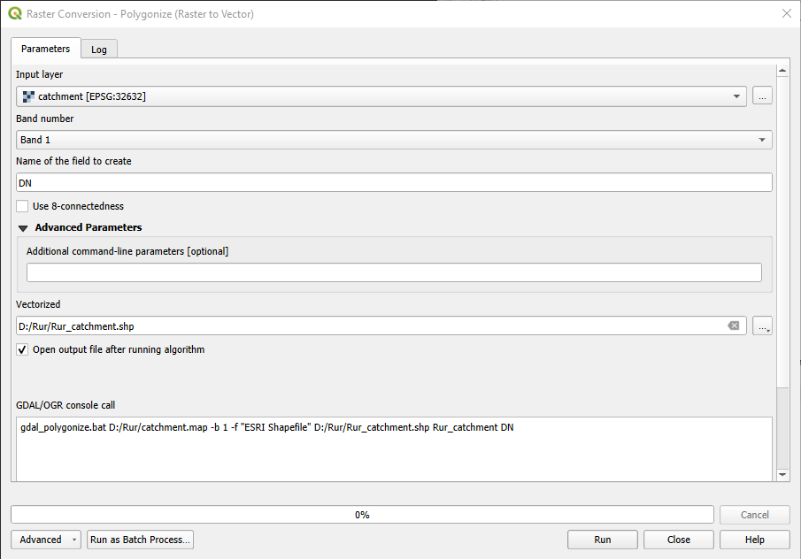
5. Make sure you choose the right
input and call the output Rur_catchment.shp. Click Run. Click Close to get back to the main screen.
6. Look at the result. Also check the attribute table (right-click on layer name and choose Open attribute table).
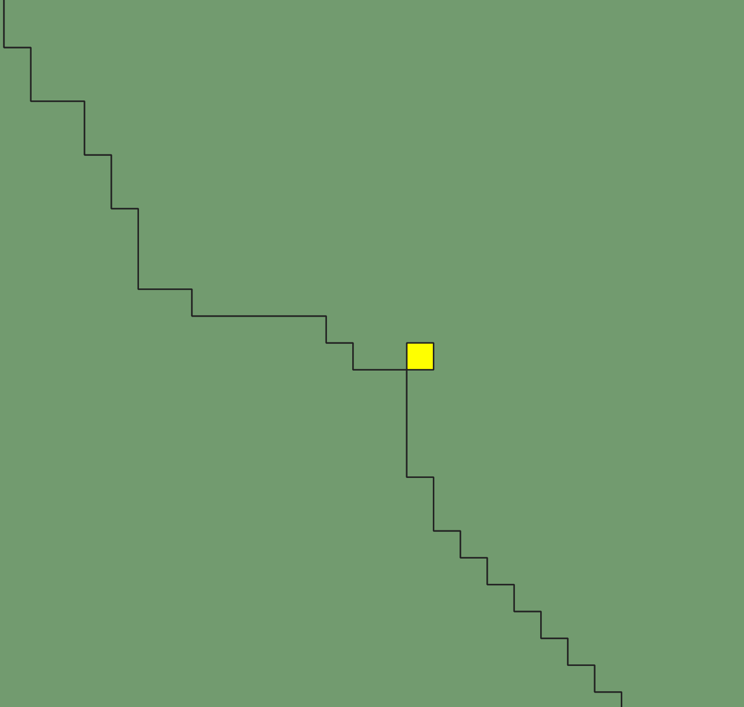
In the catchment calculation, cells belonging to the catchment get a value of 1, while the other cells get a value of 0. During the conversion to polygons, it can happen that geometry errors are introduced. If you find more than one feature with a value of 1 this indicates a geometry error (incorrect topology), because the boundary of the polygon makes a loop (see figure below). This can give errors when we use the polygon for geoprocessing. You can fix those errors with the fix geometry tool in the Processing Toolbox.
7. Close the attribute table.
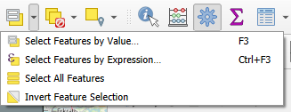
8. In the toolbar, click the Select feature by Area or Single Click tool  .
.
9. Click on the catchment polygon, so it becomes yellow.
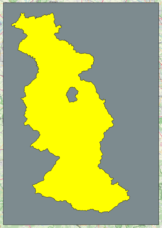
We want to keep this polygon, but remove the other ones.
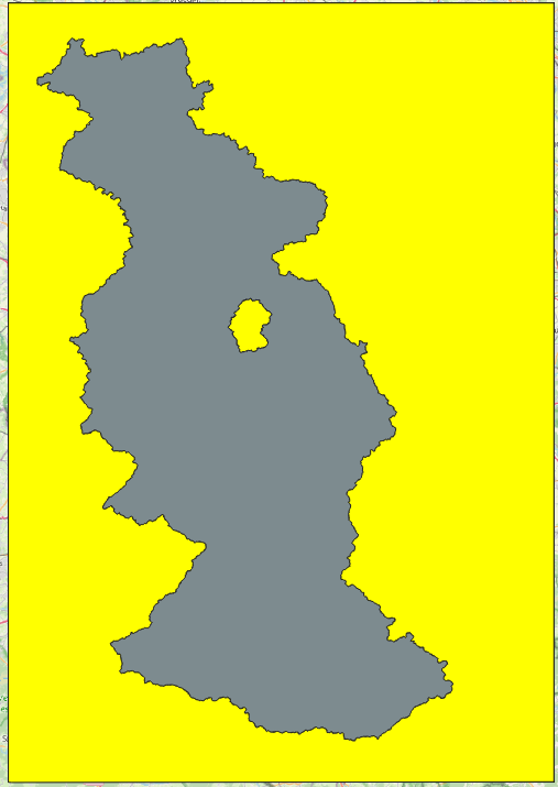
10. In the toolbar. click the Invert Feature Selection tool  .
.
Now the other polygons are yellow:
11. Click  to toggle to editing mode.
12. Click  to delete the selected polygons.
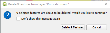
13. Confirm that you want to delete the features.
You might have noticed that the polygon has a hole. This is caused by a huge open pit lignite mine, which results in its own subcatchment in our procedure. However, we would like to see the mine as part of the delineated catchment and will correct this.
14. Enable the Advanced Digitizing Toolbar. (right-click on a toolbar and check the box before the toolbar).
15. Click the Delete Ring ![]() button and click on the
mine.
button and click on the
mine.
The hole has now disappeared.
16. Toggle off editing by clicking ![]() again, and save
the changes.
again, and save
the changes.
17. Now remove all unnecessary layers from the layers list so that we have only channels, Rur_catchment, dem_subset, hillshade and OpenStreetMap (in that order).
Watch this video to check the steps in this section: